
|
Specialists training
Biomass Energy for Heating and Hot Water Supply in Belarus (BYE/03/G31) Report on the April 2005 study tour
In the frame of the UNDP/GEF project Biomass Energy for Heating and Hot Water Supply in Belarus a one-week study tour to Austria and the Czech Republic for eight Belarusian high-level decision makers and technical specialists was organised from 3 to 10 April 2005. Study tour participants and their affiliations are presented in Table 1. Table 1: Study tour participants
The goal of the study tour was to present an overview of biomass combustion equipment and technologies produced by leading Austrian and Czech manufacturers. An intensive programme was put together by the tour organisers, summarised in Table 2, and described in more detail in the annexes. Table 2 Austrian and Czech manufacturers, plants and organisations visited
Many showcase manufacturers and flagship projects were visited within a single week. To limit the distance to be travelled by road, the tour started in Innsbruck (Austria) and finished in Prague (Czech Republic). Mr. Norbert Wildbacher and Mrs. Andrea Klammer helped organise the tour on behalf of LEV (Austria). Mrs. Michaela Remrova and Mr. John Vos helped organise the tour on behalf of BTG (Czech Republic/The Netherlands). Mrs. Michaela Remrova accompanied the group of delegates for the full duration of the tour. During the Austrian section Mr. Norbert Wildbacher also accompanied the group, whereas Mr. John Vos accompanied the group during the Czech section. The tour organisers wish to stress that the study tour merely offered the participants a Уsnapshot pictureФ. To fully understand biomass energy situation and conditions in Austria and the Czech Republic a more careful analysis is required.
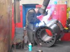
2.1 Introduction The Bertsch Group of companies was founded eighty years ago in 1925 by coppersmith master Josef Bertsch. In 1931 the firm started the production of equipment for the food and beverage industry and of high and low pressure steam boilers. In 1962 the first water pipe high-pressure steam boilers and cogeneration plants were built. In 1994 the company set-up a sales and service network in various Central and Eastern European countries. In 2001 it started the development of tailor-made concept for biomass plants. The Bertsch Holding now includes seven sister companies, including Josef Bertsch GmbH & Co. Josef Bertsch GmbH & Co is active in various sectors:
Extensive supply and performance energy technology programme. Complete problem solutions in the field of power / heat and waste heat technology, from fuel preparation via combustion with flue gas purification up to the power including plant regulation and control. The product spectrum covers medium sized hot water and/or steam boilers as well as complex cogeneration systems. The fuel range includes both conventional liquid and gaseous source of energy and biomass and waste fuels. The engineering division is specialised in strength computation, construction and manufacturing of pressure vessels, columns and heat exchangers.
Delivery and Manufacturing Programme: Boiler and Energy Technology
2.2 Selected biomass fired reference projects
As can be seen from the table, Josef Bertsch supplied the biomass cogeneration plant in Kufstein (see section 6). 2.3 Company visit Both Dr. Kurt Eller and Dr. Arno Kolbitsch, commercial and technical managing directors of the company, gave a presentation. These presentations included a general introduction of the company and the product lines as well as detailed and comprehensive data about biomass-fired steam boilers and CHP plants based on a steam turbine process. Afterwards the tour delegation went to see the production facility in Nüziders. 2.4 Contacts
3.1 Introduction MAWERA is a leading enterprise in the planning, building, installing and commissioning of automatic wood firing systems. The company has 30 years of experience using waste wood from forests and industrial waste as an energy source. With a staff of 110 MAWERA builds high quality wood fired boiler systems with capacities starting from 100 kW right through to complex, individual plant and equipment of around 10 MW capacity. The firm is able to provide all advisory and active support in seeking innovative firing problem solutions. Turnover is some € 20 million/year, of which >70% is exported. MAWERA has its own engineering and development department and an on-site testing plant. Innovative technology is developed in co-operation with technical universities and knowledge centres in Austria and abroad. Two examples include biomass CHP plants based on the Organic Rankin Cycle and on Stirling engines. The MAWERA product range includes:
Clients include industries and district heating (DH) networks in municipalities. Sales and service facilities are offered throughout Europe (including Austria, Italy, Germany, France, Switzerland, Slovenia, Poland, Russia, and the UK), in Canada and the USA. 3.2 Development of Stirling engine technology Together with BIOS BIOENERGIESYSTEME GmbH (see Section 8), MAWERA aims to develop and commercialise small-scale cogeneration technology based on Stirling engines (electrical output 35 and 70 KWel). Stirling engines can be applied in the electric capacity range 10-100 kWel, in the future maybe up to 150 kWel. Electric efficiency ranges between 6 and 20 % (currently 12-14%). Biomass CHP plants based on Stirling engines are currently at the development stage. A first Danish pilot project (elec. capacity 28 kWel) was taken into operation at TU Copenhagen in 1998/99. It ran for approximately 1,400 operating hours. The first Austrian pilot project (elec. capacity 35 kWel) was taken into operation at the MAWERA premises in September 2002. The duration test lasted 6,000 full load hours. The first demonstration plant (elec. capacity 35 kWe) was started up in December 2003. It has achieved more than 10,000 operating hours since. Under the first EU-supported Stirling engine pilot project in Austria a larger 70kWe biomass-based pilot project was taken into operation at the MAWERA premises in October 2003. The duration test with this unit lasted 5.000 hours. For 2004/2005 the realisation of the first small series of 10 units is envisaged, as well as the preparation for series production. 3.3 Reference projects in Austria
A company presentation and reports about small-scale biomass-based ORC and Stirling cogeneration technology are attached in PDF format. 3.4 Company and plant visit Mr. Claus Steurer the managing director of MAWERA presented the working fields and products of his company. Following the tour delegation visited the production plant situated nearby the headquarters. Operating MAWERA biomass boilers were visited at the CHP plants in Fussach (ORC technology) and Lingenau (Stirling technology). 3.5 Contact
The BIOSTROM biomass CHP plant in Fussach (Vorarlberg) is based on an ORC cycle and an absorption chiller for power production and cooling. Feedstock is 100% waste wood. The plant started operation in 2002. The plant is owned by Biostrom-Erzeugungs GmbH, in which the companies MAWERA and BIOS participate. 4.1 Description of the ORC cogeneration technology The principle of electricity generation by means of an ORC process corresponds to the conventional Rankine process. The substantial difference is that instead of water an organic working medium with favourable thermodynamic properties is used. The ORC process is connected with the thermal oil boiler via a thermal oil cycle. The ORC unit itself operates as a completely closed process utilising a silicon oil as organic working medium. This pressurised organic working medium is vaporised and slightly superheated by the thermal oil in the evaporator and then expanded in an axial turbine which is directly connected to an asynchronous generator. Subsequently, the expanded silicon oil passes through a regenerator (where in-cycle heat recuperation takes place) before it enters the condenser. The condensation of the working medium takes place at a temperature level which allows the heat recovered to be utilised as district or process heat (hot water feed temperature about 80 to 100-C) or in an absorption chiller. The liquid working medium then passes the feed pumps to again achieve the appropriate pressure level of the hot end of the cycle. Since the cycle of the ORC process is closed and thus no losses of the working medium are possible, the operating costs are low. Only moderate consumption-based costs (lubricants) and maintenance costs are incurred. The usual lifetime of ORC units is greater than twenty years, as has been proven by geothermal applications. The silicone oil used as working medium has the same lifetime as the ORC since it does not undergo any relevant ageing. 4.2 Technical, operational and economic data Production data
Energy input and investment costs
Technical data of the absorption chiller
4.3 Technological innovations
4.4 Scheme of the overall plant 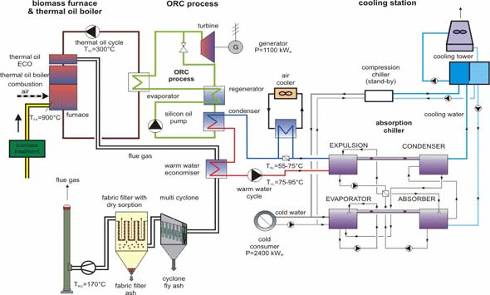
4.5 Scheme of the ORC process 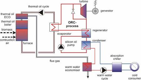
5.1 Description of the Stirling CHP Technology Stirling engines are based on a closed cycle, where the working gas is alternately compressed in a cold cylinder volume and expanded in a hot cylinder volume. The advantage of the Stirling engine over internal combustion engines is that the heat is not supplied to the cycle by combustion of the fuel inside the cylinder, but transferred from the outside through a heat exchanger in the same way as in a steam boiler. Consequently, the combustion system for a Stirling engine can be based on proven furnace technology, thus reducing combustion related problems typical of solid biomass fuels. The heat input from fuel combustion is transferred to the working gas through a hot heat exchanger at a high temperature typically between 680-C and 780-C. The heat that is not converted into work on the shaft is rejected to the cooling water in a cold heat exchanger at 25-75-C. In order to obtain a high overall electric efficiency of the CHP plant, the temperature in the hot heat exchanger should be as high as possible. Therefore, it is necessary to preheat the combustion air with the flue gas leaving the hot heat exchanger by means of an air pre-heater. Typically the temperature of the combustion air is raised to 500-600-C, resulting in very high temperatures in the combustion chamber. This can cause ash slagging and fouling problems in biomass combustion systems and in the hot heat exchanger. The closed Stirling cycle makes it possible to use a working gas, which is better suited for heat transfer to and from the cycle than air. The use of Helium or Hydrogen is most efficient, but utilisation of these low molecular weight gases makes it difficult to design a piston rod seal, which keeps the working gas inside the cylinder and prevents the lubrication oil from entering the cylinder. Many solutions have been tested, but it is still a delicate component in the engine. An attractive possibility is to bypass the problem by designing the engine as a hermetically sealed unit with the generator incorporated in the pressurised crankcase, just like the electric motor in a hermetically sealed compressor for refrigeration. Only static seals are necessary and the only connections from the inside to the outside of the hermetically sealed crankcase are the cable connections between the generator and the grid. The figure below illustrates the integration of a Stirling engine into a biomass co-generation plant 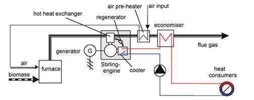
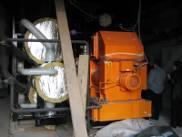
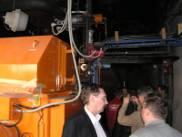
5.2 Technical and operational data The CHP plant Lingenau essentially consists of two biomass-fired boilers and a Stirling engine. An oil-fired boiler with a nominal capacity of 3,000 kW is installed for peak load coverage and as a stand-by system. The nominal thermal capacity of the biomass hot water boiler with a flat feed grate firing system is 1,100 kW and the nominal thermal capacity of the biomass-fired CHP unit is 500 kW. The furnace of the CHP unit is equipped with underfeed stoker technology. 
The 70 kWel Stirling engine, which is based on the design of the 35 kWel 4 cylinder engine, has 8 cylinders arranged in 2 squares with the cylinders parallel to each other. The asynchronous generator is incorporated in the hermetically sealed crank case just like the electric motor in a hermetically sealed compressor for refrigeration. The Stirling engine is mounted in horizontal position downstream the secondary combustion chamber for convenient maintenance. The air-preheater and the economiser are placed on top of the furnace in order to achieve a compact design of the plant. To remove fly ash particles from the hot gas heat exchanger, a pneumatic and fully automatic cleaning system has been installed. Forest and industrial wood chips from the regional forestry and wood industries are utilised as biomass fuel. The plant in Lingenau supplies a district heating network.
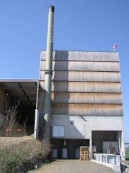
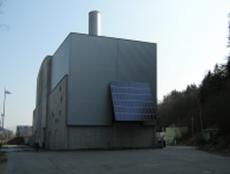
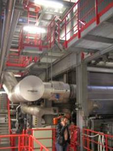
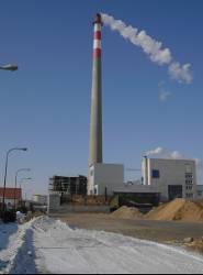
6.1 Introduction Since late 2003 Bioenergie Kufstein GmbH operates a biomass co-generation plant using a steam turbine process. Heat supply started in October 2003 and electricity supply to the local grid started in December 2003. District heat is supplied to some 4,000 customers. Feedstock used includes bark, forest wood chips, industrial wood chips, and shavings. Annual fuel demand is approx. 300,000 loose m3. The plant uses mostly wood chips with 35% moisture content bark and sawdust and other sawmill residues with a 50% moisture content. The fuel feeding system consists of a hydraulic conveying system, a vibrating cross conveyor and a chain conveyor to deliver the biomass to the charging box. The fuel is fed onto the inclined moving grate by a pusher. The water tube boiler is designed for a rate of 30 tons of live steam per hour at a live steam temperature of 450-C and a pressure of 66 bar(a). The superheated live steam is expanded in a bleeding condensing turbine with a nominal electric capacity of about 6.5 MW. The electricity produced is fed into the regional utility grid. A condenser with a maximum nominal thermal capacity of 18.0 MW supplies heat for the district heating system. 6.2 Technical data
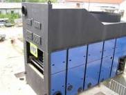
6.3 Flue gas cleaning After the removal of large fly ash particles by means of a multicyclone the flue gas of the biomass boiler arrives in the flue gas cleaning plant, composed mainly of an economiser, a wet electrostatic precipitator, and an air pre-heater. The residual heat is recovered in the economiser, whereby the flue gas is cooled down to 90-C, which flows through the wet electrostatic precipitator. The wet electrostatic precipitator cleans the flue gas to a level of particle content of about 10 mg/Nm3. Afterwards the flue gas is led to the air pre-heater where the heat exchange between flue gas and outer air occurs. Hereby the flue gas is dehumidified and the outer air is pre heated. Both gas streams are mixed within the chimney, to avoid the development of plume till an outer temperature of minus 10-C. 6.4 Tariff district heating The heat tariff in force for the heat consumers in Kufstein is given below (the original tariff sheet in German is attached in PDF format). Consumers have to pay a combined rate including a demand rate, a kilowatt hour rate, a meter charge and the turnover tax of 20%.
6.5 Contact
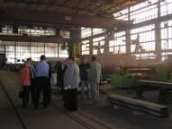
7.1 Introduction Binder is one of Austria's leading biomass boiler manufacturers and has been active since 1981. On its 2 premises spread over 11 ha and with 6200 m2 of shopfloor area, Binder manufactures more than 200 boiler systems per year for commercial, industrial and residential applications. Binder boilers are fully automated, highly efficient, reliable and cost-effective. They are installed all over the world - from Canada to Russia. A family firm, the company has always put the emphasis on top quality engineering and reliability. The co-operation with nearby university facilities and related organisations, and the know-how of its highly-skilled 100-plus employees secure the high technological standard of Binder boilers. There are more than 3000 Binder heating boilers, with total capacity of more than 1000 MW, in operation around the world. Reliable service and maintenance is provided through the service team headquartered in Bärnbach and supplied by 13 sales and service organisations in 11 countries. These include exclusive distributors that have been trained to install, commission, operate and maintain the systems. Boiler capacities range from 12 to 10,000 kW (and even larger on special order). The range begins with pellet boilers in the 25kW to 75kW scale, suitable for applications such as family homes, nursery schools and small businesses. The range expands to wood chip and pellet boilers for medium and large commercial applications right up to the multi-megawatt scale suitable for district heating and industry. Binder boilers are used across Europe and North America in leisure, timber, local authority, residential care, retail and large housing developments. A major benefit of choosing a Binder boiler is that as a systems supplier, Binder provides and installs complete boiler systems - from the fuel container to the stainless-steel chimney, from the accumulator tank to the fully-fledged, mobile and containerised heating centre - with all the components produced and tested in-house. Binder thus offers a complete turnkey engineering package for biomass heating systems 7.2 Binder Boiler Range Binder boilers employ the very latest technology in terms of combustion design and control to provide efficiencies in the order of 92%. The boiler construction relies on high quality materials used in under-stressed construction resulting in expected life span of >20 years. Binder boilers come in a wide range of frame and capacity sizes. Above 3MW, the actual configuration will vary according to the particular site. Systems for up to 10MW can be supplied. 7.3 Fuel Supply Options Binder heating systems can work with a wide variety of fuel supply arrangements. The smaller wood pellet boilers usually operate with either a combined fuel magazine or a fuel silo in close proximity. For small to medium sized systems, the fuel supply options can include above or below ground stores with rotary agitators (agitators up to 7.5m). For large commercial fuel stores walking floors (up to 500m³ capacity and beyond) can be provided. 7.4 Company visit At the company Binder the tour delegation got a company presentation and guided tour to the places of production in Russian language.
7.5 Contact
8.1 Introduction
8.2 Working fields
8.3 Selected References
A company brochure of BIOS BIOENERGIESYSTEME GmbH in English is attached in PDF format. 8.4 Company visit The presentation included some key information about the company, the working fields and selected references of BIOS. Afterwards a technical discussion about topics which are of note for the tour delegation took place.
8.5 Contact
9.1 Introduction The Business Unit Fuel Engineering is an independently led division of the company Herz-Armaturen GmbH. Since more than twenty years the business unit builds and sells biomass heating systems. As pioneers in the field of biomass use the business unit has gained extensive experiences. The business unit runs a modern research laboratory, which is used to remain leading in the field of renewable energy. Customers are taken care of in close co-operation with mother company Herz-Armaturen which has an extensive network of offices in many Western and Eastern European countries Biomass plants are offered in the capacity range 3-500 KW. The plants are manufactured in Sebersdorf. The automatic plants Pelletstar, Pelletfire, Firematic and Biomatic are planned and installed by heating system fitters. The region of operation includes Austria, Germany, Italy, Switzerland, Belgium and other countries. Customers (household owners, medium-sized collective buildings and heating networks) can rely on a European-wide service and advisory network
9.2 Company visits Dr. Morteza Fesharaki, Head of Research and Development, welcomed the delegation. A tour was given of the factory where armatures (Herz' main activity) are produced and biomass boilers are assembled. Afterwards the Herz supplied biomass boiler in Neckenmarkt was visited. 9.3 Contacts
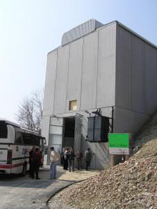
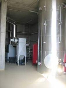
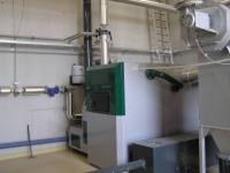
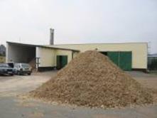
10 Biomass heating plant, Neckenmarkt The village of Neckenmarkt (population 1785, altitude 225m), located in Burgenland close to the Hungarian border, is well-known for wine-growing. Since a few months the village has a biomass heating plant, supplied by Herz. The plant is owned by a biomass heating co-operative. Construction of the biomass plant, which is located on a mountain slope, started on 22 October 2004 and was completed within 8 weeks. The plant has been in operation since. Two Herz boilers of 400 kW each are installed. The plant will operate all year. To minimise labour demand for operation plant control, boiler cleaning and ash discharge are automated. Heat is supplied to a total of 37 customers, mainly households but also some larger consumers (winegrowers, church buildings).
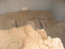
Fuel storage and supply Each of the 36 co-operative members supplies fuel (chipped hardwood) to the plant, which has a large storage room (capacity 880 m3). It can be filled from a loading platform at the top. Because it is built on a mountain slope filing the storage room from the top is very easy and straightforward, using gravity. Spring blade rotary stirrers covey the fuel from the bottom of the storage room to the boilers Financial issues The total investment in the village heating system amounted to approx. 950,000 Euro. Subsidies from Burgenland and the Austrian State covered 40%. Co-operative members paid on average some € 8000 each. The remaining investment costs are covered from a long-term commercial bank loan.
Because the plant is co-operatively owned and to minimise tax payments the heat price is set each year so that overall the annual profits are (close to) zero. It is calculated that customers will need to be pay on average € 800-1000 per heating season, i.e. only half of the € 1600-2000 they would pay for gas or oil based heat-supply.
TEDOM is a private Czech company owned by four individuals persons, each owning 25%. TEDOM has been operating in the area of communal and industrial energy supply since 1991. In more than 500 projects it has installed more than 1100 co-generation units with an overall electric output of more than 100 MW. While the mother company TEDOM s.r.o. concentrates mainly on the development, manufacturer and sale of co-generation units, its subsidiary companies are mainly involved with project financing, reconstruction and the operation of heat-energy systems and sources of central heat supply. TEDOM Holding TEDOM s.r.o. is one of the main producers and operators of decentralised co-generation plants in Europe. Co-generation units are manufactured in three output series: PREMI (10-50 kW), CENTO (40-240 kW) and QUANTO (> 200kW). A series of micro-generation plants is under development, both with piston engines and with its own Stirling engine. TEDOM is headquartered in Výčapy near Třebíč (Vysočina region) where sales, service and operation of co-generation units take place. Manufacturing of co-generation units takes place in Hořovice (Central Bohemia region). Mid 2003 TEDOM acquired the former LIAZ gas engine factory in Jablonec nad Nisou (Northern Bohemia region). During the last few years increasing attention is paid to co-generation units that use renewable sources of energy, including sewage gas from water treatment, landfill gas from MSW disposal and biogas from animal manure digestion. TEDOM project references in this field include the € 4.5 million landfill gas cogeneration project in Getline, Latvia (6730 kWth, 4240 kWe), the Ďáblice and Chabry landfills near Prague, and the biogas project at a pig farm in Velké Albrectice. TEDOM has also sold 3 biogas plants to the Gu An Farm Gu in Hebei Provincie, China. The TEDOM holding group also includes several companies in which it holds shares. Examples are: TEDOM Energie s.r.o., TENERGO Brno a.s., Teplo Ivančice s.r.o., and Jesenická tepelná sploečnost s.r.o., all of which operate town district heating systems. TEDOM Energie also provides project financing and produces renewable electricity. Also part of the TEDOM holding group are TTS energo, TTS cz and TTS eko. TTS energo s.r.o. generates heat and electricity for the town of Třebíč. TTS eko s.r.o. manufacturers biomass boilers. The TTS group (Tøebíèská Tepelná Spoleènost) is run independently. The table illustrates the annual production of electricity and heat by the companies that are part of the TEDOM holding (base year 2003)
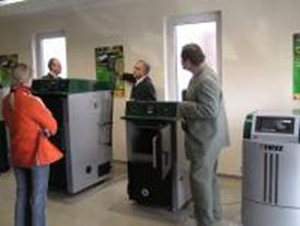
Company visit Mr. Vlado Murár, the company's marketing manager, gave a presentation. The presentation covered a general introduction of the holding company, its manufacturing and energy supply activities, and case studies of some interesting cogeneration projects. In the showroom demonstration models of the CENTO and the QUANTO cogeneration units were observed.
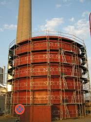
TTS eko, TTS cz and TTS energo are part of the TEDOM group (see previous section) since 2003 but they are operated independently. TTS eko s.r.o. delivers biomass boilers houses for power supply and district heating energy on turn-key basis since 1993. The company was originally known as NUCLEA s.r.o. TTS energy s.r.o. runs the heat supply system of the town of Třebíč on the basis of a contract with the town since 1994. 12.1 TTS eko s.r.o. TTS eko supplies turn-key biomass boilers for power supply and district heating. Its VESKO-B hot water boilers cover the capacity range 1-7 MW. VESKO-B boilers are applied as central heat supply system and can be operated on various types of biomass (e.g. wood or straw). A new product is the Organic Rankine Cycle module for cogeneration from biomass in the 0.2-1.5 MW range. In April 2004 TTS will install an ORC module at the K13 boiler house heating system in Třebíč 12.2 TTS energo s.r.o. TTS energy s.r.o. runs the heating system of the town of Třebíč. Part of the district heat is generated at boiler house K13. This boiler house was initially fully natural gas fired. In 2001 a 3 MW biomass boiler was installed as demonstration plant. In 2004 the biomass boiler was run nearly full time and supplied 20% of the generated heat.
With the financial support of the State Environment Fund, a second and much larger (7 MW) biomass boiler was installed in December 2004. The biomass boiler replaces am old, low-efficient natural gas boiler. It ran successfully for 4 months. At the time of the visit in April 2005, the new biomass boiler was not in operation as it was being expanded with a 1.1 MWe ORC module.
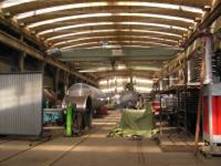
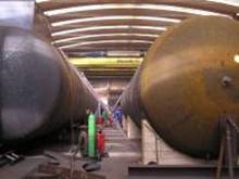
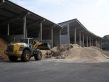
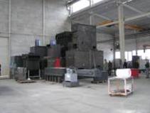
12.3 Company visit Mr. Mlejnek, a TTS representative, gave a detailed tour of the boiler house premises, including the wood storage site, the gas boiler room, the two biomass boiler rooms, and the room where the Organic Rankine Cycle module was under construction.
13.1 Introduction HAMONT Consulting & Engineering GmbH in Graz (Austria) is the sales partner for Central and Eastern Europe and Sweden of the leading Austrian biomass boiler company KWB Kraft und Wärme aus Biomasse GmbH. With a staff of some 90 people, the sister company HAMONT Contracting and Trading spol. s r.o. in Frydek-Mistek (Czech Republic) builds biomass boilers in the 15-500 kW capacity range. Almost eighty percent of the production is exported to Austria where the component parts of the boilers are assembled and subsequently sold to customers in Austria, Germany, Switzerland, Italy, Slovenia etc. The remainder is sold on the markets targeted by HAMONT Consulting & Engineering Boilers of up to 100 kW for burning biomass (pellets, chips, sawdust and other wood waste) are manufactured according to the design of the Austrian companies KWB and ÖkoFEN. Boilers in the 125-500 kW capacity range are based on KWB experience on wood combustion and heat-exchanging methods but developed in-company. Since 1999 the Czech home market is targeted, in particular the 100-500 kW capacity range. Dozens of boiler-houses in the country have been equipped with automatic Hamont boilers. In 2003, the company began expanding its operations to the Slovak Republic. Further expansion to other countries in Northern and Eastern Europe is targeted (Poland, Estonia, Lithuania, Latvia, Sweden, and others).
13.2 Reference projects 350 kW wood chip boiler in Tranovické sluzby s.r.o, Czech Republic. 500 kW grass boiler in Roznovská travni semena sro. in Roznov, Czech Republic. 350 kW wood chip boiler in Moravany u Kyjova - obecny urad, Czech Republic. 100 kW wood chip boiler in Poloma/Presov, Slovakia 2x 350 kW wood chip boilers, School for Forest-Engineering, Sigord, Slovakia Kraft und Wärme aus Biomasse GmbH, Austria The origin of KWB dates back to Dr. August Raggam of TU Graz who dedicated himself to the research of biomass combustion. This research work led to the founding of KWB in 1994. In 2004 KWB employed 71 staff and sold more than 2000 biomass heating systems (sales value € 16.6 million). KWB systems are now available all over Central Europe. Sales and services are provided by over 21 sales representative partners and 1500 heating engineers and heating system fitters. KWB manufactures and supplies the following products
A wide range of fuel feeding systems is available (elbow worm conveyor, spring blade rotary stirrer, articulated blade rotary stirrer, hopper suction system or storage container). 13.3 Company visit The company visit included various activities. First Mr. Friedrich Harrich, accompanied by Mr. Folvarny, gave an introduction on the HAMONT philosophy. This was followed by a visit to the biomass boiler that heats the HAMONT premises. Next the production plant was toured, followed by a company presentation at the office. Afterwards HAMONT invited the delegation to a lunch at a local restaurant. 13.4 Contact Dipl-Ing. Friedrich Harrich
14.1 Introduction Vyncke is a family-owned company established in 1912. The company is now run by the 4th generation of Vyncke. Vyncke has as its mission to convert biomass and industrial waste into clean process energy. It offers combustion technology, boiler construction and control technology all under one roof. Vyncke provides design, engineering, manufacturing, installation, commissioning and training through after sales service all from a single source Vyncke is unique in its sector, offering flexibility and tailor made solutions from 0.5 to 100 MWth, adhering to strictest emission regulations. Energy produced can be steam or hot water, thermal oil, hot gas or electrical energy in any combination (multi-media), from a wide range of fuels (coarse or fine, wet or dry) in virtually any combination. Fuels that may be used include agro-industrial residues (from processing sunflowers, palm oil, corn, rice, cotton, peanut, coocnut, tobacco, wheat, etc.) and secondary fuels (bark, municipal solid waste, rice husk, pelletised industrial waste, demolition wood, empty fruit bunches).
Customers (more than 3000 world-wide) are found in a range of industries, and served through 4 business units:
14.2 Products Vyncke offers customised solutions. The Vyncke systems make use of:
The heart of a Vyncke boiler is the patented Dynamic Watercooled Stepgrate. It offers several advantages: largest fuel flexibility (fine and coarse, wet and dry), low emissions, high efficiency, long lifetime, low maintenance, and fully automatic de-ashing 14.3 Reference projects
14.4 Company visit Vyncke Manager Mr. Petr Salvet gave a presentation on the company and its activities, followed by a guided tour of the production plant. 14.5 Contacts
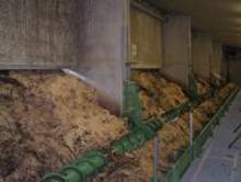
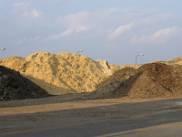
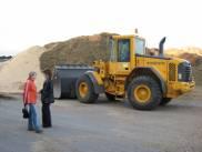
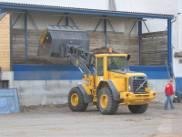
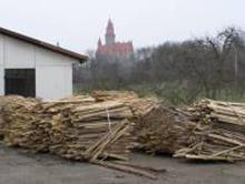
A company brochure in Russian is attached in PDF format. 15 BIOMASS HEATing PLANT bouzov Description When the premises of a bankrupt company at the local industrial area became vacant the decision was made to install a village biomass heating system here that would replace the individual coal stoves. Two biomass boilers, of 1800 kW and 600 KW each, were installed by VERNER in 2001. A closed-cycle heat distribution network, with a total length of approx. 5 km, was also installed. Water is supplied at 85oC and returns at 75oC, thus ensuring minimal heat losses. Today 98% of the households are connected. There are some 120 heat substations including 85 for family houses and the remainder for municipal and other buildings. Connection of Bouzov castle is foreseen for 2005. In the near future heating capacity may be expanded by adding a third, 900 kW biomass boiler. The extra boiler would supply newly built houses as well as a swimming pool, construction of which is under consideration. Fuel supply Fuels used consist of 70% solid industrial wood waste (slabs, - 550 Kr/ton) and some 30% forestry chips (- 1000 Kr/ton). In addition, some straw and some Rumex (an energy crop) is combusted. To feed the latter fuels to the biomass boiler a dedicated chain conveyor is used. Fuel consumption amounts to some 10 ton per day (tpd) in winter and some 10 ton twice a week in summer. The capacity of the short-term fuel storage is around 10 tpd. At the site there is sufficient storage to store biomass for several months, both under roof and in the open air. No long-term fuel supply contracts have been signed. It is considered that there is sufficient biomass available in the region to be ensured from an uninterrupted biomass supply. Operational issues The boiler is operated automatically. In case of a failure a signal is send by GSM telephone. In the beginning there were some teething problems but now the biomass boiler performs satisfactorily. If operational problems occur these are mainly caused by the fuel supply (e.g. contamination of the wood chips by a piece of metal). Practical lessons learned include:
Financial issues The total investment amounted to 45 million Kr. (1.5 million Euro), as follows:
Installation of the 5km heating network required some 5 million Kr. per kilometre. The costs of buildings were modest as use was made of existing buildings. Investment costs are covered from 3 sources:
The project is part of the ERUPT bio-energy project portfolio developed by BTG, which means that the realised carbon emission reductions are sold to the Dutch Government. The latter makes available advance payments up to 60% of the anticipated value of the reduced carbon emissions. By trading the carbon credits some 15% of the investment costs (or the bulk of the commercial loan) may be recovered. In the 2004/2005 heating season, heat is being sold for 250 Kr/GJ (8.33 И/GJ), which compares very favourably with the 330 Kr/GJ (11 € /GJ) which is commonly paid by urban consumers for natural gas based heat supply. Previously the households paid something between 13,000 and 25,000 Kr (433-833 € ) for space heating per year. Visit Mayor Mr. Foltyn welcomed the Belarusian delegation at the town hall. He informed the group about the project background. Later VERNER representative Mr. Zapadlo, who had travelled from Červený Kostelec, joined the group. Following the introduction, the biomass heating plant was visited.
Introduction
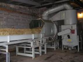
References Boilers are available in the capacities: 350 kW, 600 kW, 900 KW, 1800 kW and combinations of these. Typical fuels include sawdust, woodchips, and straw. Common applications include sawmills and wood processing industries, other factories, pelleting and briquetting lines, schools, and hospitals. Boilers are sold to customers in Sweden, Lithuania, Austria, Germany, Denmark, Poland, Czech Republic, Slovakia and other European countries. Company Visit The Belarusian delegation was given a tour of the company showroom. Several smaller-scale pellet and wood chips boilers were introduced. This was followed by a visit under the guidance of Mr. Zapadlo to the biomass boiler that heats the VERNER premises. Various types of feedstock are used in the biomass boiler, including straw. A planned tour of the factory hall could not go ahead as due to the late arrival of the delegation the factory was closed already. 17 BTG Biomass Technology Group
17.1 BTG Biomass Technology Group BV BTG Biomass Technology Group BV (BTG) is specialised in the conversion of biomass into useful fuels and energy. The professional BTG staff consists of consulting engineers, researchers and business developers that are fully dedicated to bio-energy system development and implementation. Together the BTG experts cover the entire biomass technology chain, from research & development to commercial implementation. Fields of expertise include thermal and biological energy conversion processes, biofuels production, biomass logistics, and biomass based heating and electrification. Services offered address the technical, economic, financial, environmental, legal and organisational aspects of bio-energy systems and projects, including:
Since its establishment in 1979, BTG has completed assignments in more than 80 countries. Examples include the Benelux, China, Costa Rica, and many countries in Central and Eastern Europe (Belarus, Bulgaria, Croatia, Czech Republic, Estonia, Georgia, Hungary, Moldova, Poland, Russia, Slovak Republic, and Ukraine). The experience gained in these countries has generated valuable insight in the possibilities and difficulties of realising bio-energy projects around the globe. Examples include:
Feasibility studies. BTG carries out feasibility studies aimed at evaluating the renewable energy generation potential, suitable conversion technologies and financial viability. Common elements of these studies include: assessment of biomass availability, quality and prices; technology assessments; evaluation of the potential energy generation; evaluation of the financial feasibility, and elaboration of a business and investment plan Carbon consulting. BTG helps clients effectively develop greenhouse gas emission reduction projects. Following closely the progress of the CO2 emission market and the Kyoto Protocol agenda, BTG provides the most up-to-date GHG project consultancy:
The BTG Carbon Consulting team takes advantage of a network of partners across many countries of the EU, Central and Eastern Europe, Latin America and Asia. One of its successes has been the development of a portfolio of fuel substitution projects in the Czech Republic for which it secured a multimillion Euro carbon trading contract. Technology Assessments. BTG carries out bio-energy technology assessments for private and the public sector clients. Such studies assess the state of the art, the R&D needs, anticipated developments, and the future opportunities and potential to convert biomass into solid, gaseous and liquid energy carriers in a region, country, continent or economic sector. Strategic studies. BTG has initiated and co-ordinated strategic studies aimed at assisting public and private sector clients developing biomass energy policies and portfolios. Examples include the European Energy Crops Network project, the Bio-energy Market Development Strategy for CEE Countries, the Rainbow Biomass Technology Assessment Study, the Bio-energyТs role in the EU Energy Market Assessment Study, and the Network on Thermal Biomass Conversion and Implementation Technology Development. BTGТs research is aimed at developing marketable technologies for the production of heat, electricity, transportation fuels and chemicals from biomass. The research efforts have led to a number of patented technologies such as the rotating-cone reactor for the production of pyrolysis oil or the reverse-flow reactor for the cleaning of producer gas. Current research activities are focused on scaling-up and commercialisation of the pyrolysis process for bio-oil production, and on bio-oil applications. Once ready for commercialisation, technologies are marketed through licensing or through spin-off companies in which BTG maintains a share. As a company dedicated to developing innovative bio-energy technologies and bringing these to the market, BTG has direct insight, knowledge and experience of the many factors that can hamper the growth of the bio-energy sector. 17.2 BTG Central Europe s.r.o. The Prague Office of BTG Biomass Technology Group was established in 2000 to facilitate the expansion of BTG activities in Central and Eastern Europe. Its principal activities include energy and environment consultancy services, project development and training in the field of renewable energy. The Prague Office carries out work on local projects as well as international activities in teams with experts from other BTG offices and BTG partners. Within BTG, the Prague Office has been developing the greenhouse gas expertise.
Development of Joint Implementation (JI) and Clean Development Mechanism (CDM) portfolios in the Czech Republic and elsewhere is one of the major activities of the Prague Office. One of its successes has been the joint development with BTG headquarters of a portfolio of fuel substitution projects in the Czech Republic for which a multimillion Euro carbon trading contract has been secured. A company brochure of BTG is attached in PDF format. 17.3 Company visit Michaela Remrova, Manager of the BTG office in Prague, gave a presentation on BTG's Czech bio-energy project portfolio, for which it has secured carbon credits funding under the Joint Implementation programme of the Dutch Government Afterwards the delegates discussed the status of ratification of the Kyoto protocol by Belarus. Finally they briefly evaluated the study tour. | ||||||||||||||||||||||||||||||||||||||||||||||||||||||||||||||||||||||||||||||||||||||||||||||||||||||||||||||||||||||||||||||||||||||||||||||||||||||||||||||||||||||||||||||||||||||||||||||||||||||||||||||||||||||||||||||||||||||||||||||||||||||||||||||||||||||||||||||||||||||||||||||||||||||||||||||||||||||||||||||||||||||||||||||||||||||||||||||||||||||||||||||||||||||||||||||||||||||||||||||||||||||||||||||||||||||||||||||||||||||||||||||||||||||||||||||||||||||||||||||||||||||||||||||||||||||||||


 |
 |